Getting started with grid graphs
How to set up your first grid graph and using it in a scene.

We'll create a scene with some obstacles, add a grid graph to it, and then add an agent that can move around in the scene.
We'll base it on the same scene as in the Get Started Guide, but we'll use a GridGraph instead of a RecastGraph.
If you have just followed the Get Started Guide, you can keep your scene, but delete your recast graph.
Contents
- Example scenes with grid graphs
- Creating a scene with some obstacles
- Adding Pathfinding
- Adjusting the graph to our scene
- How the grid graph works
- Adding an agent
- But what if I want grid-based movement?
- What about layered grid graphs?
- Conclusion
Example scenes with grid graphs
The package includes a few example scenes with grid graphs:
Hexagonal Turn Based (hexagonal graphs are just a type of grid graph)
Creating a scene with some obstacles
Create a new empty scene, name it "PathfindingTest".
The agent needs something to walk on, and something for it to avoid.

Add a plane to the scene, place it at the scene origin (0,0,0) and scale it to (10,10,10).
Then create some cubes of different scales and place them on the plane; these will be obstacles which the agent should avoid.
You can optionally add some materials to the objects, to make them look nicer.
Your scene should now look something like in the image
Adding Pathfinding
Add a new empty GameObject to the scene, name it "A*".
Attach the AstarPath component to the GameObject.
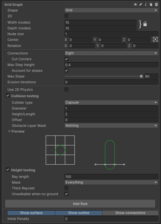
Open the A* inspector, and add a new GridGraph.
Click on the graph's label to expand its settings.
Adjusting the graph to our scene
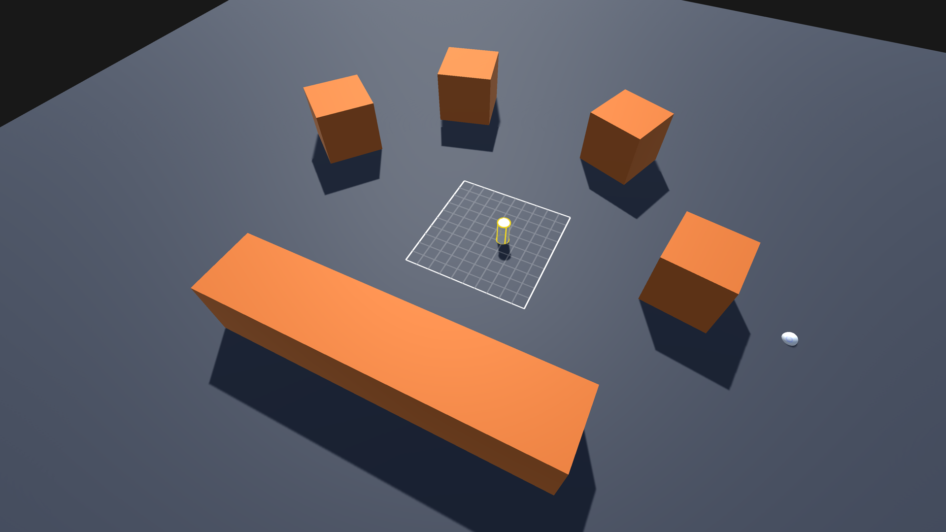
The graph is not scanned yet, but it has a visualization for where the grid will be placed, once it is scanned.
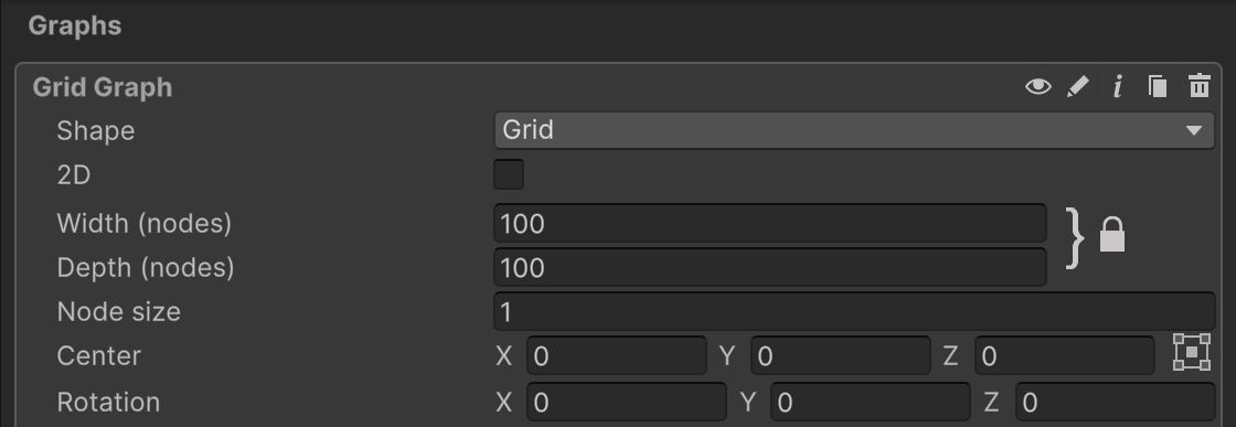
You can make a normal rectangular grid, an isometric grid, or even make it use hexagonal nodes.
You can also adjust the size of the grid, as well as its center and rotation. The position, rotation and size can also be adjusted using the normal tools in the scene view.

Set the Width and Depth settings to 100, so that it covers our scene.
Leave the Node Size at 1, the default.
You can also use the 3D scale tool in the scene view to drag the bounds to cover the scene.
Now we are ready to scan the graph.
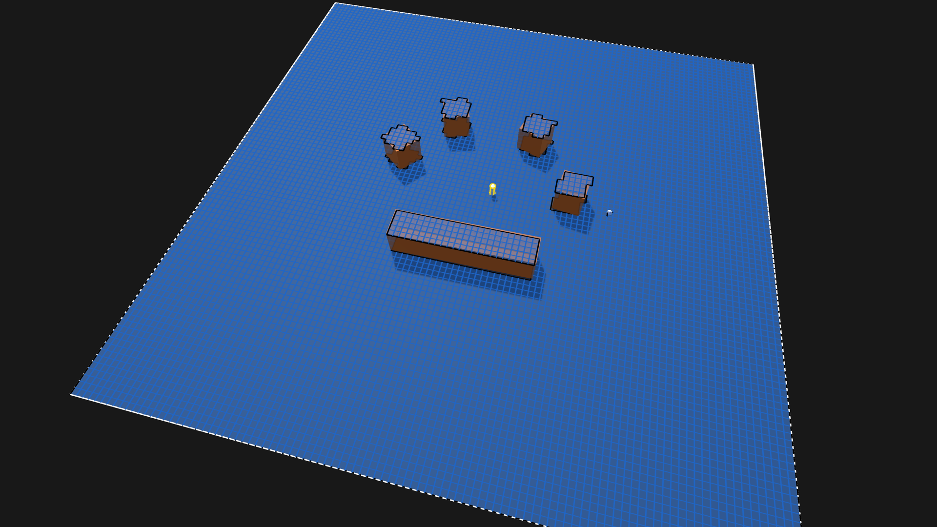
Click Scan.
Or use the shortcut ctrl+alt+s (windows) or cmd+alt+s (mac).
The graph will now be scanned, and you should see a blue grid covering the scene.
The grid graph is, by default, configured to treat everything as ground, but nothing as obstacles. This works for many games, as height differences alone can be enough.
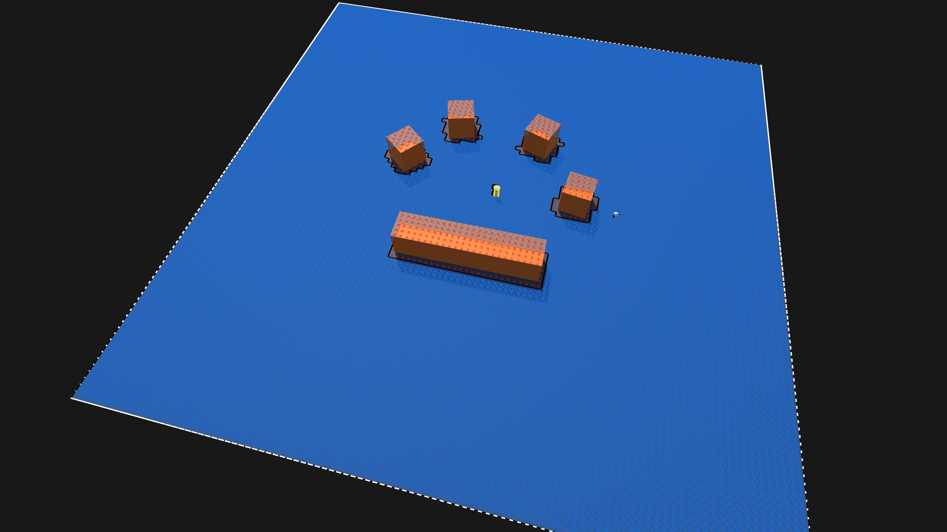
But let's assume, for our scene, that we want the cubes to be treated as obstacles, so that the agent cannot even walk on them. We can do this by changing the Collision Testing settings.
Move the cubes to a separate layer, any layer other than the default will do. Use for example Ignore Raycast.
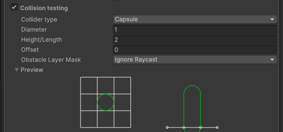
In the graph's collision testing settings, change the Obstacle Layer Mask to the layer that the cubes are on.
Set Collision Testing → Diameter to 2
This will add some margin around obstacles, so that the agent doesn't get too close to them.
The inspector contains a preview of the collision testing shape, both a top-down view, and a side view.
Scan the graph.
In the scene view, you should now see small red cubes indicating nodes that are unwalkable.


As mentioned, using just the height differences between the nodes can often be enough, especially when combined with the Erosion Iterations setting. Try this:
Disable Collision Testing in the graph settings.
Set Erosion Iterations to 2.
Scan the graph.
All ledges, or unwalkable nodes, will now be eroded by 2 nodes, creating more unwalkable nodes around them.
This has the benefit of preventing the agent from getting too close to ledges, in addition to obstacles.
How the grid graph works
The grid graph divides the world into a grid of nodes.
In contrast to e.g. the navmesh and recast graphs, which define the walkable areas by where their triangles are, nodes exist over the whole grid graph, but each node can be either walkable or unwalkable.
Unwalkable nodes are shown in the scene view as small red cubes.
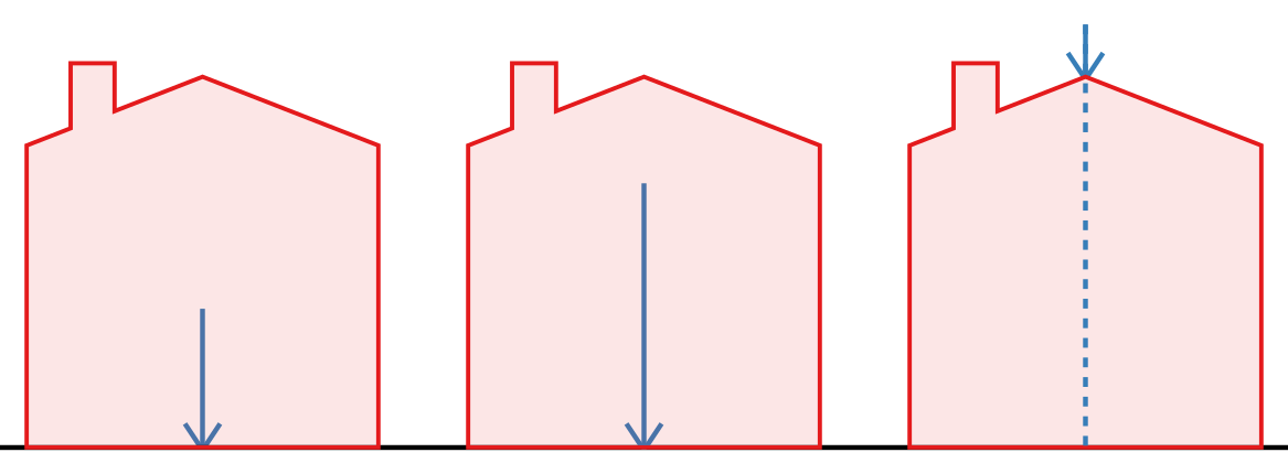
If the node is sloping too much, it can be made unwalkable immediately.

There are a few different collision shapes that can be used, but the most common one is a capsule shape.

Connections can be filtered out, if the step height would be too high, or if a diagonal would cut a corner to an unwalkable node.
Adding an agent
Now that we have a graph, we can add an agent to the scene.
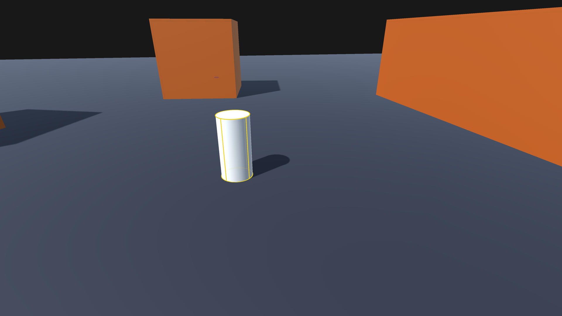
Create a new GameObject and name it "Agent"
Place it somewhere on the ground
Attach the FollowerEntity component to the agent's root GameObject
If you do not have the Unity Entities package installed, the inspector will prompt you to install it.
The FollowerEntity requires the entities package, but there are other movement scripts in the package that don't.
Add a Cylinder object as a child of the agent, and move it to (0,1,0). This will make it line up with the FollowerEntity's bounds.

Attach the AIDestinationSetter component to the agent.
We'll also need a target for the agent to move to.
Create a new Sphere object, name it Target.
Place it somewhere in the scene, where you want the agent to move.
Assign the Target GameObject to the "Target" field on the AIDestinationSetter component.
Now, if you press play, the agent should move towards the target.
But what if I want grid-based movement?
If you want the agent to move along the grid, you'll have to use a different movement script.
The FollowerEntity is a great movement script, but it is intended for smooth movement in any direction.
We can instead use the AIPath movement script.
The AILerp movement script is also a good choice, if you don't want any physics or local avoidance. It follows the path exactly, without any deviations. The AIPath script still uses some smoothing.
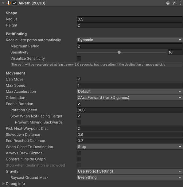
Remove the FollowerEntity component from the agent.
Attach the AIPath component to the agent.
This will also automatically attach the Seeker component, which helps the AIPath component with pathfinding.
Increase the AIPath → Max Speed setting to 5.
Now, if you press play, the agent should move towards the target.
You'll notice, however, that it doesn't follow the path super closely, and the path can also have a lot of turns in it when the path is not completely straight or completely diagonal. With grid-based movement, you often want your paths to be a bit cleaner.
Fortunately, we can remedy this by just a few changes.
Reduce AIPath → Pick Next Waypoint Distance to 1.
This will make the agent follow the path a bit more closely.
Set Seeker → Start End Modifier → End Point Snapping to Node Center.
This will make the agent always move to the node centers, instead of to its exact destination.
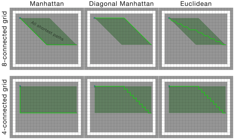
Select the A* object and set A* Inspector → Settings → Pathfinding → Heuristic to Diagonal Manhattan.
This will change how the algorithm breaks ties between alternative paths of the same length. On 8-connected grid graphs, DiagonalManhattan will give cleaner paths, while Euclidean will make the path move straighter towards the target.
Press play.
The agent should now move to the target, and follow the grid more closely.
What about layered grid graphs?
Layered grid graphs work just like normal grid graphs, but they can have multiple layers of nodes on top of each other. This is good for handling environments like a house with multiple floors.
Regular grid graphs are slightly more efficient in terms of memory and performance, but they can't handle overlapping areas.
This is an A* Pathfinding Project Pro feature only. This function/class/variable might not exist in the Free version of the A* Pathfinding Project or the functionality might be limited.
The Pro version can be bought here
Conclusion
You made it to the end! We have covered how to create a scene with some obstacles, add a grid graph to it, and then add an agent that can move around in the scene. We have also covered how to use the AIPath movement script, which can be useful for grid-based movement.