Public
Generates a grid of nodes.
 The GridGraph does exactly what the name implies, generates nodes in a grid pattern.
Grid graphs are excellent for when you already have a grid-based world. But they also work well for free-form worlds.
Features
Throw any scene at it, and with minimal configurations you can get a good graph from it.
Predictable pattern.
Grid graphs work well with penalties and tags.
You can update parts of the graph during runtime.
Graph updates are fast.
Scanning the graph is comparatively fast.
Supports linecasting.
Supports the funnel modifier.
Supports both 2D and 3D physics.
Supports isometric and hexagonal node layouts.
Can apply penalty and walkability values from a supplied image.
Perfect for terrains since it can make nodes walkable or unwalkable depending on the slope.
Only supports a single layer, but you can use a LayerGridGraph if you need more layers.
Inspector
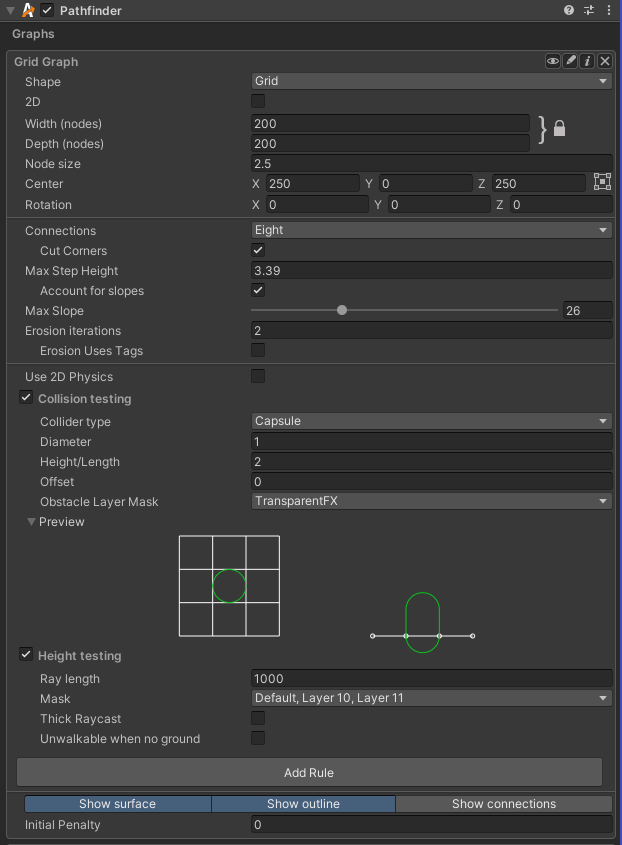
A grid graph can be set up as a normal grid, isometric grid or hexagonal grid. Each of these modes use a slightly different inspector layout. When changing the shape in the inspector, it will automatically set other relevant fields to appropriate values. For example, when setting the shape to hexagonal it will automatically set the neighbours field to Six.
This field is only used in the editor, it has no effect on the rest of the game whatsoever.
If you want to change the grid shape like in the inspector you can use the SetGridShape method.
NoteThis is just a convenience property, this property will actually read/modify the rotation of the graph. A rotation aligned with the 2D plane is what determines if the graph is 2D or not.
SeeYou can also set if the graph should use 2D physics using `this.collision.use2D` ( GraphCollision.use2D).
See
This setting corresponds to the member
is2D
This is very handy if your game uses a tilemap for rendering and you want to make sure the graph is laid out exactly the same. Matching grid parameters manually can be quite tricky in some cases.
The inspector will automatically show a button to align to a tilemap if one is detected in the scene. If no tilemap is detected, the button be hidden.

Grid graphs are typically anywhere from 10-500 nodes wide. But it can go up to 1024 nodes wide by default. Consider using a recast graph instead, if you find yourself needing a very high resolution grid.
This value will be clamped to at most 1024 unless ASTAR_LARGER_GRIDS has been enabled in the A* Inspector -> Optimizations tab.
See
This setting corresponds to the member
width
Grid graphs are typically anywhere from 10-500 nodes wide. But it can go up to 1024 nodes wide by default. Consider using a recast graph instead, if you find yourself needing a very high resolution grid.
This value will be clamped to at most 1024 unless ASTAR_LARGER_GRIDS has been enabled in the A* Inspector -> Optimizations tab.
See
This setting corresponds to the member
depth
For a grid layout, this is the length of the sides of the grid squares.
For a hexagonal layout, this value does not correspond to any specific dimension of the hexagon. Instead you can convert it to a dimension on a hexagon using ConvertNodeSizeToHexagonSize.
See
This setting corresponds to the member
nodeSize
This should be used if you want different scales on the X and Y axis of the grid
This option is only visible in the inspector if the graph shape is set to isometric or advanced.
If you are making a 2D isometric game, you may want to use this parameter to adjust the layout of the graph to match your game. This will essentially scale the graph along one of its diagonals to produce something like this:
A perspective view of an isometric graph. 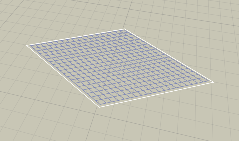
A top down view of an isometric graph. Note that the graph is entirely 2D, there is no perspective in this image. 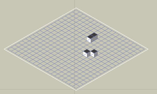
For commonly used values see StandardIsometricAngle and StandardDimetricAngle.
Usually the angle that you want to use is either 30 degrees (alternatively 90-30 = 60 degrees) or atan(1/sqrt(2)) which is approximately 35.264 degrees (alternatively 90 - 35.264 = 54.736 degrees). You might also want to rotate the graph plus or minus 45 degrees around the Y axis to get the oritientation required for your game.
You can read more about it on the wikipedia page linked below.
This option is only visible in the inspector if the graph shape is set to isometric or advanced.
The graph can be positioned anywhere in the world.
See
This setting corresponds to the member
center
The nodes are laid out along the X and Z axes of the rotation.
For a 2D game, the rotation will typically be set to (-90, 270, 90). If the graph is aligned with the XY plane, the inspector will automatically switch to 2D mode.
See
This setting corresponds to the member
rotation
Either four, six, eight connections per node.
Six connections is primarily for hexagonal graphs.
See
This setting corresponds to the member
neighbours
If this is true, and neighbours is set to Eight, obstacle corners are allowed to be cut by a connection.
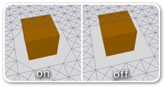
See
This setting corresponds to the member
cutCorners
Set to 0 to ignore the value.
This affects for example how the graph is generated around ledges and stairs.
VersionWas previously called maxClimb
When this is enabled the normals of the terrain will be used to make more accurate estimates of how large the steps are between adjacent nodes.
When this is disabled then calculated step between two nodes is their y coordinate difference. This may be inaccurate, especially at the start of steep slopes.

In the image below you can see an example of what happens near a ramp. In the topmost image the ramp is not connected with the rest of the graph which is obviously not what we want. In the middle image an attempt has been made to raise the max step height while keeping maxStepUsesSlope disabled. However this causes too many connections to be added. The agent should not be able to go up the ramp from the side. Finally in the bottommost image the maxStepHeight has been restored to the original value but maxStepUsesSlope has been enabled. This configuration handles the ramp in a much smarter way. Note that all the values in the image are just example values, they may be different for your scene. 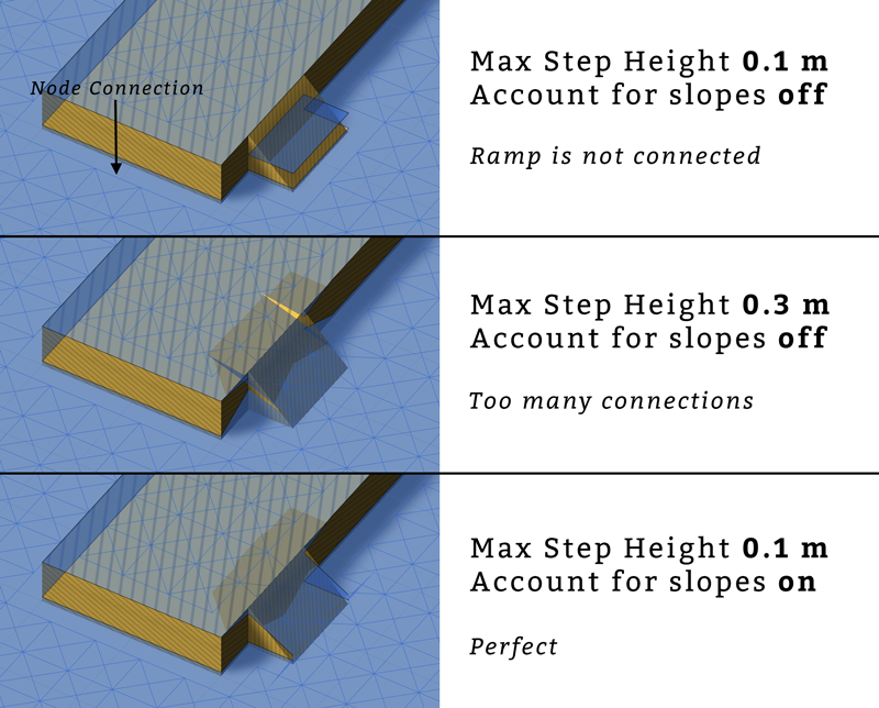
See
This setting corresponds to the member
maxSlope
The graph can be eroded to add extra margin to obstacles. It is very convenient if your graph contains ledges, and where the walkable nodes without erosion are too close to the edge.
Below is an image showing a graph with 0, 1 and 2 erosion iterations: 
NoteA high number of erosion iterations can slow down graph updates during runtime. This is because the region that is updated needs to be expanded by the erosion iterations times two to account for possible changes in the border nodes.
If enabled, the 2D Physics API will be used, and if disabled, the 3D Physics API will be used.
This changes the collider types (see type) from 3D versions to their corresponding 2D versions. For example the sphere shape becomes a circle.
The heightCheck setting will be ignored when 2D physics is used.
Collision testing
When checking for collisions the system will check if any colliders overlap a specific shape at the node's position. The shape is determined by the type field.
A diameter of 1 means that the shape has a diameter equal to the node's width, or in other words it is equal to nodeSize .
If type is set to Ray, this does not affect anything.
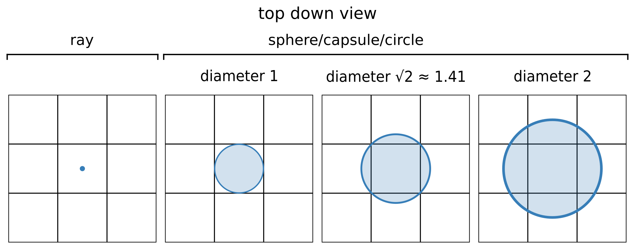
If type is set to Sphere, this does not affect anything.

WarningIn contrast to Unity's capsule collider and character controller this height does not include the end spheres of the capsule, but only the cylinder part. This is mostly for historical reasons.
For example, if the ground was found at y=0, collisionOffset = 2 type = Capsule and height = 3 then the physics system will be queried to see if there are any colliders in a capsule for which the bottom sphere that is made up of is centered at y=2 and the top sphere has its center at y=2+3=5.
If type = Sphere then the sphere's center would be at y=2 in this case.

On the left you can see a top-down view of the graph with a grid of nodes. On the right you can see a side view of the graph. The white line at the bottom is the base of the graph, with node positions indicated using small dots. When using 2D physics, only the top-down view is visible.
The green shape indicates the shape that will be used for collision checking.
Height testing
As the image below visualizes, different ray lengths can make the ray hit different things. The distance is measured up from the graph plane.
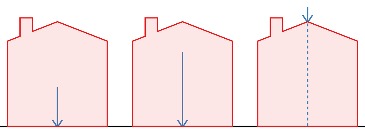
If height raycast is turned off, this doesn't affect anything.
Rules
Take a look at Grid Graph Rules for a list of available rules.
Other settings
Each node will be drawn as a square (unless e.g hexagon graph mode has been enabled).
Updating the graph during runtime
Any graph which implements the IUpdatableGraph interface can be updated during runtime. For grid graphs this is a great feature since you can update only a small part of the grid without causing any lag like a complete rescan would.
If you for example just have instantiated an obstacle in the scene and you want to update the grid where that obstacle was instantiated, you can do this:
AstarPath.active.UpdateGraphs (obstacle.collider.bounds);
Where obstacle is the GameObject you just instantiated.
As you can see, the UpdateGraphs function takes a Bounds parameter and it will send an update call to all updateable graphs.
A grid graph will assume anything could have changed inside that bounding box, and recalculate all nodes that could possibly be affected. Thus it may end up updating a few more nodes than just those covered by the bounding box.
Hexagonal graphs
The graph can be configured to work like a hexagon graph with some simple settings. The grid graph has a Shape dropdown. If you set it to 'Hexagonal' the graph will behave as a hexagon graph. Often you may want to rotate the graph +45 or -45 degrees. 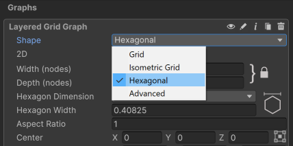
NoteSnapping to the closest node is not exactly as you would expect in a real hexagon graph, but it is close enough that you will likely not notice.
A grid graph can be added and configured completely at runtime via code.
// This holds all graph data
AstarData data = AstarPath.active.data;

// This creates a Grid Graph
GridGraph gg = data.AddGraph(typeof(GridGraph)) as GridGraph;

// Setup a grid graph with some values
int width = 50;
int depth = 50;
float nodeSize = 1;

gg.center = new Vector3(10, 0, 0);

// Updates internal size from the above values
gg.SetDimensions(width, depth, nodeSize);

// Scans all graphs
AstarPath.active.Scan();
Tree colliders
It seems that Unity will only generate tree colliders at runtime when the game is started. For this reason, the grid graph will not pick up tree colliders when outside of play mode but it will pick them up once the game starts. If it still does not pick them up make sure that the trees actually have colliders attached to them and that the tree prefabs are in the correct layer (the layer should be included in the 'Collision Testing' mask).
Inner Types
Public Methods
Calculates the grid connections for a cell as well as its neighbours.
A random point on the graph.
Public Static Methods
Public Variables
int
LayerCount
Number of layers in the graph.
For grid graphs this is always 1, for layered grid graphs it can be higher. The nodes array has the size width*depth*layerCount.
float
aspectRatio = 1F
Scaling of the graph along the X axis.
This should be used if you want different scales on the X and Y axis of the grid
This option is only visible in the inspector if the graph shape is set to isometric or advanced.
World bounding box for the graph.
This always contains the whole graph.
NoteSince this is an axis-aligned bounding box, it may not be particularly tight if the graph is significantly rotated.
Center point of the grid in world space.
The graph can be positioned anywhere in the world.
Settings on how to check for walkability and height.
bool
cutCorners = true
If disabled, will not cut corners on obstacles.
If this is true, and neighbours is set to Eight, obstacle corners are allowed to be cut by a connection.

int
depth
Depth (height) of the grid in nodes.
Grid graphs are typically anywhere from 10-500 nodes wide. But it can go up to 1024 nodes wide by default. Consider using a recast graph instead, if you find yourself needing a very high resolution grid.
This value will be clamped to at most 1024 unless ASTAR_LARGER_GRIDS has been enabled in the A* Inspector -> Optimizations tab.
int
erodeIterations
Number of times to erode the graph.
The graph can be eroded to add extra margin to obstacles. It is very convenient if your graph contains ledges, and where the walkable nodes without erosion are too close to the edge.
Below is an image showing a graph with 0, 1 and 2 erosion iterations: 
NoteA high number of erosion iterations can slow down graph updates during runtime. This is because the region that is updated needs to be expanded by the erosion iterations times two to account for possible changes in the border nodes.
int
erosionFirstTag = 1
Tag to start from when using tags for erosion.
InspectorGridMode
inspectorGridMode = InspectorGridMode.Grid
Determines the layout of the grid graph inspector in the Unity Editor.
A grid graph can be set up as a normal grid, isometric grid or hexagonal grid. Each of these modes use a slightly different inspector layout. When changing the shape in the inspector, it will automatically set other relevant fields to appropriate values. For example, when setting the shape to hexagonal it will automatically set the neighbours field to Six.
This field is only used in the editor, it has no effect on the rest of the game whatsoever.
If you want to change the grid shape like in the inspector you can use the SetGridShape method.
InspectorGridHexagonNodeSize
inspectorHexagonSizeMode = InspectorGridHexagonNodeSize.Width
Determines how the size of each hexagon is set in the inspector.
For hexagons the normal nodeSize field doesn't really correspond to anything specific on the hexagon's geometry, so this enum is used to give the user the opportunity to adjust more concrete dimensions of the hexagons without having to pull out a calculator to calculate all the square roots and complicated conversion factors.
This field is only used in the graph inspector, the nodeSize field will always use the same internal units. If you want to set the node size through code then you can use ConvertHexagonSizeToNodeSize.

bool?
is2D
Get or set if the graph should be in 2D mode.
NoteThis is just a convenience property, this property will actually read/modify the rotation of the graph. A rotation aligned with the 2D plane is what determines if the graph is 2D or not.
SeeYou can also set if the graph should use 2D physics using `this.collision.use2D` ( GraphCollision.use2D).
bool
isScanned
True if the graph has been scanned and contains nodes.
Graphs are typically scanned when the game starts, but they can also be scanned manually.
If a graph has not been scanned, it does not contain any nodes and it not possible to use it for pathfinding.
float
isometricAngle
Angle in degrees to use for the isometric projection.
If you are making a 2D isometric game, you may want to use this parameter to adjust the layout of the graph to match your game. This will essentially scale the graph along one of its diagonals to produce something like this:
A perspective view of an isometric graph. 
A top down view of an isometric graph. Note that the graph is entirely 2D, there is no perspective in this image. 
For commonly used values see StandardIsometricAngle and StandardDimetricAngle.
Usually the angle that you want to use is either 30 degrees (alternatively 90-30 = 60 degrees) or atan(1/sqrt(2)) which is approximately 35.264 degrees (alternatively 90 - 35.264 = 54.736 degrees). You might also want to rotate the graph plus or minus 45 degrees around the Y axis to get the oritientation required for your game.
You can read more about it on the wikipedia page linked below.
This option is only visible in the inspector if the graph shape is set to isometric or advanced.
float
maxSlope = 90
The max slope in degrees for a node to be walkable.
float
maxStepHeight = 0.4F
The max y coordinate difference between two nodes to enable a connection.
Set to 0 to ignore the value.
This affects for example how the graph is generated around ledges and stairs.
VersionWas previously called maxClimb
bool
maxStepUsesSlope = true
Take the slope into account for maxStepHeight.
When this is enabled the normals of the terrain will be used to make more accurate estimates of how large the steps are between adjacent nodes.
When this is disabled then calculated step between two nodes is their y coordinate difference. This may be inaccurate, especially at the start of steep slopes.

In the image below you can see an example of what happens near a ramp. In the topmost image the ramp is not connected with the rest of the graph which is obviously not what we want. In the middle image an attempt has been made to raise the max step height while keeping maxStepUsesSlope disabled. However this causes too many connections to be added. The agent should not be able to go up the ramp from the side. Finally in the bottommost image the maxStepHeight has been restored to the original value but maxStepUsesSlope has been enabled. This configuration handles the ramp in a much smarter way. Note that all the values in the image are just example values, they may be different for your scene. 
uint[]
neighbourCosts = new uint[8]
Costs to neighbour nodes.
See neighbourOffsets.
int[]
neighbourOffsets = new int[8]
Index offset to get neighbour nodes.
Added to a node's index to get a neighbour node index.
        Z
        |
        |

     6  2  5
      \ | /
--  3 - X - 1  ----- X
      / | \
     7  0  4

        |
        |
NumNeighbours
neighbours = NumNeighbours.Eight
Number of neighbours for each node.
Either four, six, eight connections per node.
Six connections is primarily for hexagonal graphs.
float
nodeSize = 1
Size of one node in world units.
For a grid layout, this is the length of the sides of the grid squares.
For a hexagonal layout, this value does not correspond to any specific dimension of the hexagon. Instead you can convert it to a dimension on a hexagon using ConvertNodeSizeToHexagonSize.
All nodes in this graph.
Nodes are laid out row by row.
The first node has grid coordinates X=0, Z=0, the second one X=1, Z=0
the last one has grid coordinates X=width-1, Z=depth-1.
var gg = AstarPath.active.data.gridGraph;
int x = 5;
int z = 8;
GridNodeBase node = gg.nodes[z*gg.width + x];
Rotation of the grid in degrees.
The nodes are laid out along the X and Z axes of the rotation.
For a 2D game, the rotation will typically be set to (-90, 270, 90). If the graph is aligned with the XY plane, the inspector will automatically switch to 2D mode.
bool
showMeshOutline = true
Show an outline of the grid nodes in the Unity Editor.
bool
showMeshSurface = true
Show the surface of the graph.
Each node will be drawn as a square (unless e.g hexagon graph mode has been enabled).
bool
showNodeConnections
Show the connections between the grid nodes in the Unity Editor.
Size of the grid.
Will always be positive and larger than nodeSize.
Vector2
unclampedSize = new Vector2(10, 10)
Size of the grid.
Can be negative or smaller than nodeSize
int
width
Width of the grid in nodes.
Grid graphs are typically anywhere from 10-500 nodes wide. But it can go up to 1024 nodes wide by default. Consider using a recast graph instead, if you find yourself needing a very high resolution grid.
This value will be clamped to at most 1024 unless ASTAR_LARGER_GRIDS has been enabled in the A* Inspector -> Optimizations tab.
Public Static Variables
const int
FixedPrecisionScale = 1024
Scaling used for the coordinates in the Linecast methods that take normalized points using integer coordinates.
To convert from world space, each coordinate is multiplied by this factor and then rounded to the nearest integer.
Typically you do not need to use this constant yourself, instead use the Linecast overloads that do not take integer coordinates.
float
StandardDimetricAngle = Mathf.Acos(1/2f)*Mathf.Rad2Deg
Commonly used value for isometricAngle.
float
StandardIsometricAngle = 90-Mathf.Atan(1/Mathf.Sqrt(2))*Mathf.Rad2Deg
Commonly used value for isometricAngle.
int[]
neighbourXOffsets = { 0, 1, 0, -1, 1, 1, -1, -1 }
Offsets in the X direction for neighbour nodes.
Only 1, 0 or -1
int[]
neighbourZOffsets = { -1, 0, 1, 0, -1, 1, 1, -1 }
Offsets in the Z direction for neighbour nodes.
Only 1, 0 or -1
Public Enums
RecalculationMode
RecalculateFromScratch |
Recalculates the nodes from scratch.
Used when the graph is first scanned. You should have destroyed all existing nodes before updating the graph with this mode. |
RecalculateMinimal |
Recalculate the minimal number of nodes necessary to guarantee changes inside the graph update's bounding box are taken into account.
Some data may be read from the existing nodes |
NoRecalculation |
Nodes are not recalculated.
Used for graph updates which only set node properties |
Inherited Public Members
Reference to the AstarPath object in the scene.
World bounding box for the graph.
This always contains the whole graph.
NoteSince this an axis aligned bounding box, it may not be particularly tight if the graph is rotated.
It is ok for a graph type to return an infinitely large bounding box, but this may make some operations less efficient. The point graph will always return an infinitely large bounding box.
bool
drawGizmos = true
Enable to draw gizmos in the Unity scene view.
In the inspector this value corresponds to the state of the 'eye' icon in the top left corner of every graph inspector.
uint
graphIndex
Index of the graph, used for identification purposes.
Used as an ID of the graph, considered to be unique.
NoteThis is Pathfinding.Util.Guid not System.Guid. A replacement for System.Guid was coded for better compatibility with iOS
bool
infoScreenOpen
Used in the editor to check if the info screen is open.
Should be inside UNITY_EDITOR only #ifs but just in case anyone tries to serialize a NavGraph instance using Unity, I have left it like this as it would otherwise cause a crash when building. Version 3.0.8.1 was released because of this bug only
uint
initialPenalty
Default penalty to apply to all nodes.
string
name
Name of the graph.
Can be set in the unity editor
bool
open
Is the graph open in the editor.
bool
persistent
True if the graph will be included when serializing graph data.
If false, the graph will be ignored when saving graph data.
Most graphs are persistent, but the LinkGraph is not persistent because links are always re-created from components at runtime.
bool
showInInspector
True if the graph should be visible in the editor.
False is used for some internal graph types that users don't have to worry about.
Private/Protected Members
const int
HexagonConnectionMask = 0b010101111
Mask based on hexagonNeighbourIndices.
This indicates which connections (out of the 8 standard ones) should be enabled for hexagonal graphs.
int hexagonConnectionMask = 0;
for (int i = 0; i < GridGraph.hexagonNeighbourIndices.Length; i++) hexagonConnectionMask |= 1 << GridGraph.hexagonNeighbourIndices[i];
int[]
allNeighbourIndices = { 0, 1, 2, 3, 4, 5, 6, 7 }
Which neighbours are going to be used when neighbours=8.
int[]
axisAlignedNeighbourIndices = { 0, 1, 2, 3 }
Which neighbours are going to be used when neighbours=4.
bool
exists
True if the graph exists, false if it has been destroyed.
int[]
hexagonNeighbourIndices = { 0, 1, 5, 2, 3, 7 }
Which neighbours are going to be used when neighbours=6.
System.Func<GridNodeBase>
newGridNodeDelegate = () => new GridNode()
Delegate which creates and returns a single instance of the node type for this graph.
This may be set in the constructor for graphs inheriting from the GridGraph to change the node type of the graph.
Internal data for each node.
It also contains some data not stored in the node objects, such as normals for the surface of the graph. These normals need to be saved when the maxStepUsesSlope option is enabled for graph updates to work.
bool
useRaycastNormal
Use heigh raycasting normal for max slope calculation.
True if maxSlope is less than 90 degrees.
Deprecated Members
float
maxClimb
The max y coordinate difference between two nodes to enable a connection.
float
penaltyAngleFactor = 100F
How much penalty is applied depending on the slope of the terrain.
At a 90 degree slope (not that exactly 90 degree slopes can occur, but almost 90 degree), this penalty is applied. At a 45 degree slope, half of this is applied and so on. Note that you may require very large values, a value of 1000 is equivalent to the cost of moving 1 world unit.
float
penaltyAnglePower = 1
How much extra to penalize very steep angles.
bool
penaltyPosition
Use position (y-coordinate) to calculate penalty.
DeprecatedUse the RuleElevationPenalty class instead
float
penaltyPositionFactor = 1F
Scale factor for penalty when calculating from position.
float
penaltyPositionOffset
Offset for the position when calculating penalty.
DeprecatedUse the RuleElevationPenalty class instead
Holds settings for using a texture as source for a grid graph.
Texure data can be used for fine grained control over how the graph will look. It can be used for positioning, penalty and walkability control.
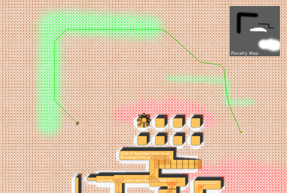
Below is a screenshot of a grid graph with a penalty map applied. It has the effect of the AI taking the longer path along the green (low penalty) areas.
 Color data is got as 0...255 values.
A* Pro FeatureThis is an A* Pathfinding Project Pro feature only. This function/class/variable might not exist in the Free version of the A* Pathfinding Project or the functionality might be limited.
The Pro version can be bought here
WarningCan only be used with Unity 3.4 and up
DeprecatedUse the RuleTexture class instead
 The GridGraph does exactly what the name implies, generates nodes in a grid pattern.





 Color data is got as 0...255 values.