Writing Graph Generators
All graphs in the A* Pathfinding Project are written as add-ons to the system, this makes it (relatively) easy to add your own specialized graph types.
In this tutorial I will show you how to set up a basic Graph Generator which you can use with the system.
The complete script can be found here PolarGraphGenerator.cs
A Basic Graph
The simplest graph possible looks like this: using System.Collections.Generic;
using UnityEngine;
using Pathfinding;
using Pathfinding.Serialization;
using Pathfinding.Util;
// Inherit our new graph from the base graph type
[JsonOptIn]
// Make sure the class is not stripped out when using code stripping (see https://docs.unity3d.com/Manual/ManagedCodeStripping.html)
[Pathfinding.Util.Preserve]
public class SimpleGraph : NavGraph {
protected override IEnumerable<Progress> ScanInternal () {
// Here we will place our code for scanning the graph
yield break;
}
public override void GetNodes (System.Action<GraphNode> action) {
// This method should call the delegate with all nodes in the graph
}
}
This graph will not generate any nodes, but it should show up greyed out in the Add New Graph list
So let's start creating some scanning logic!
Scanning
First, create a new script containing the code above, but rename it to PolarGraph and save it as PolarGraph.cs.
The ScanInternal method is called when the graph should be scanned. A Scan method should create a number of nodes and create connections between them. We will create a Polar Graph, i.e sort of like a grid, but laid out as a circle with rings instead of rows. I will use "circles" to denote the number of concentric rings in the graph and "steps" as the number of nodes in each circle. Note that in the image below, what you are seeing are the connections between the nodes. The nodes themselves are placed at the intersections between those line segments. 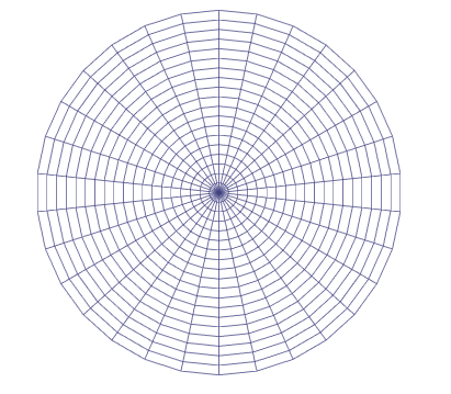
The first step is to create a tempoary array for holding the nodes and add some variables for configuring the graph. We will use the PointNode node type which is used by the PointGraph since it contains essentially the same things that we want to use.
public int circles = 10;
public int steps = 20;

public Vector3 center = Vector3.zero;
public float scale = 2;

// Here we will store all nodes in the graph
PointNode[] nodes;

GraphTransform transform;

// Create a single node at the specified position
PointNode CreateNode (Vector3 position) {
    var node = new PointNode(active);
    // Node positions are stored as Int3. We can convert a Vector3 to an Int3 like this
    node.position = (Int3)position;
    return node;
}

public override IEnumerable<Progress> ScanInternal () {
    // Create a 2D array which will contain all nodes
    // This is just a tempoary array to make it easier to reference different nodes
    PointNode[][] circleNodes = new PointNode[circles][];
    yield break;
}
Editor
The graph does not yet show up in the Add New Graph list because that requires a graph editor which we will create now. Create a new script in either AstarPathfindingProject/Editor/GraphEditors/ (or if you have enabled Js support AstarPathfindingEditor/Editor/GraphEditors/) or in any other Editor folder.
Name the script PolarGeneratorEditor.cs
Below is a very simple editor for the polar graph. Copy this code into the file you just crated. After you have done this you should be able to create the graph. using UnityEditor;
using Pathfinding;
[CustomGraphEditor(typeof(PolarGraph), "Polar Graph")]
public class PolarGeneratorEditor : GraphEditor {
// Here goes the GUI
public override void OnInspectorGUI (NavGraph target) {
var graph = target as PolarGraph;
graph.circles = EditorGUILayout.IntField("Circles", graph.circles);
graph.steps = EditorGUILayout.IntField("Steps", graph.steps);
graph.scale = EditorGUILayout.FloatField("Scale", graph.scale);
graph.center = EditorGUILayout.Vector3Field("Center", graph.center);
}
}
The CustomGraphInspector attribute tells the system that this class is a custom editor for the graph of type PolarGraph, the display-name in the graphs list will be "Polar Graph".
Try it out! Open the Graphs tab in the AstarPath inspector, click Add Graph, and add the Polar Graph which should be in the list now.
Adding nodes
Now we need to get to work with actually creating a graph. Every code fragment below this point should go into the Scan function.
We will use a matrix for placement to enable rotation, positioning and so on of the nodes.
The first node in the array should be the center node which we will place at Vector3.zero. Node positions are stored as Int3s. They are like Vector3s but use integer coordinates instead of floating point coordinates. There is an explicit cast available between Vector3 and Int3.
// Create a 2D array which will contain all nodes
// This is just a tempoary array to make it easier to reference different nodes
PointNode[][] circleNodes = new PointNode[circles][];

// Create a matrix which just moves the nodes to #center
// and scales their positions by #scale
// The GraphTransform class has various utility methods for working with it
transform = new GraphTransform(Matrix4x4.TRS(center, Quaternion.identity, Vector3.one*scale));

// Place the center node in the center
circleNodes[0] = new PointNode[] {
    CreateNode(CalculateNodePosition(0, 0, transform))
};
static Vector3 CalculateNodePosition (int circle, float angle, GraphTransform transform) { Now we will set up the rest of the graph, circle for circle, node for node
// Get the direction towards the node from the center
var pos = new Vector3(Mathf.Sin(angle), 0, Mathf.Cos(angle));
// Multiply it with the circle number to get the node position in graph space
pos *= circle;
// Multiply it with the matrix to get the node position in world space
pos = transform.Transform(pos);
return pos;
}// The size of the angle (in radians) each step will use Now we have set up all the nodes to their correct positions, but they have no connections to other nodes, so let's add that:
float anglesPerStep = (2*Mathf.PI)/steps;
for (int circle = 1; circle < circles; circle++) {
circleNodes[circle] = new PointNode[steps];
for (int step = 0; step < steps; step++) {
// Get the angle to the node relative to the center
float angle = step * anglesPerStep;
Vector3 pos = CalculateNodePosition(circle, angle, transform);
circleNodes[circle][step] = CreateNode(pos);
}
}
// Iterate through all circles The first node (the center) is a special case, it will have connections to all nodes in the first circle (or second depending on how you look at it).
// circle 0 is just the center node so we skip that for now
for (int circle = 1; circle < circles; circle++) {
for (int step = 0; step < steps; step++) {
// Get the current node
PointNode node = circleNodes[circle][step];
// The nodes here will always have exactly four connections, like a grid, but polar.
// Except for those in the last circle which will only have three connections
int numConnections = circle < circles-1 ? 4 : 3;
var connections = new Connection[numConnections];
// Get the next clockwise node in the current circle.
// The last node in each circle should be linked to the first node
// in the circle which is why we use the modulo operator.
connections[0].node = circleNodes[circle][(step+1) % steps];
// Counter clockwise node. Here we check for underflow instead
connections[1].node = circleNodes[circle][(step-1+steps) % steps];
// The node in the previous circle (in towards the center)
if (circle > 1) {
connections[2].node = circleNodes[circle-1][step];
} else {
// Create a connection to the middle node, special case
connections[2].node = circleNodes[circle-1][0];
}
// Are there any more circles outside this one?
if (numConnections == 4) {
// The node in the next circle (out from the center)
connections[3].node = circleNodes[circle+1][step];
}
for (int q = 0; q < connections.Length; q++) {
// Node.position is an Int3, here we get the cost of moving between the two positions
connections[q].cost = (uint)(node.position-connections[q].node.position).costMagnitude;
}
node.connections = connections;
}
}
This means that it will have steps connections, because steps is the number of nodes in each circle. // The center node is a special case, so we have to deal with it separately Now the only thing left to do, is to make the nodes walkable, the default value is unwalkable. This tutorial will not cover the checking for obstacles or similar, but if you read up on Unity's Physics class you should be able to get that working.
PointNode centerNode = circleNodes[0][0];
centerNode.connections = new Connection[steps];
// Assign all nodes in the first circle as connections to the center node
for (int step = 0; step < steps; step++) {
centerNode.connections[step] = new Connection(
circleNodes[1][step],
// centerNode.position is an Int3, here we get the cost of moving between the two positions
(uint)(centerNode.position-circleNodes[1][step].position).costMagnitude
);
}// Store all nodes in the nodes array If you have placed all the previous snippets after each other in the Scan function like I wrote before, you will have a working scan function.
List<PointNode> allNodes = new List<PointNode>();
for (int i = 0; i < circleNodes.Length; i++) {
allNodes.AddRange(circleNodes[i]);
}
nodes = allNodes.ToArray();
// Set all the nodes to be walkable
for (int i = 0; i < nodes.Length; i++) {
nodes[i].Walkable = true;
}
Finally to be able to scan the graph the GetNodes method needs to be implemented. Since all our nodes are just stored in an array, it is very simple.
public override void GetNodes (System.Action<GraphNode> action) { You should be able to create the graph, edit the parameters and if you click Scan the graph will appear in the Scene View.
if (nodes == null) return;
for (int i = 0; i < nodes.Length; i++) {
// Call the delegate
action(nodes[i]);
}
}
Cool huh?
However, you might notice that if you deselect the inspector and then select it again, your settings have not been saved.
This is because we need to add one last thing, serialization.
All graph settings are serialized to JSON (see http://www.json.org/). For the fields to get serialized, we must add an attribute to each field. The JsonMember attribute will tell the serializer that we want to serialize that field.
The complete script can be found here PolarGraphGenerator.cs
More Stuff
More methods can be overridden to customize other functionality. Especially the GetNearest and GetNearestForce methods. Which control how the nearest node to a point is found. There is a default implementation but it will search through all nodes in the graph every time which can be a bit slow if your graph contains a lot of nodes. You can also override the OnDrawGizmos method if you want to draw the graph differently than the default implementation.
If you need to serialize more information, you can override the SerializeExtraInfo, DeserializeExtraInfo and if you need to set up nodes after they have been loaded, you can override the PostDeserialization function.
Explaining all functions is beyond the scope of this tutorial, you can have a look at how other graph types have implemented them.
The End
You should now be able to use this graph like any other graph!
I hope this tutorial has helped you get started writing graph generators.